|
Problems in Tribology and Materials
Science of Friction Composites
| | 
http://mpri.org.by |
|
Energy dissipation during frictional interaction
Investigation directions
- prediction of thermal load on the friction contact
- elaboration of physico-chemical principles of optimizing structure and properties of matrix polymer
- use of ecologically safe reinforcing fibrous components
- improvement of efficiency reliability and comfort of frictional interaction (braking)
- lowering vibroacoustic activity of friction devices
- optimization of design of friction parts by strength and reliability criteria
- provision of quality of materials and products during production
- monitoring of materials and tribosystems
- economics of tribosystems
|
|
SEM photomicrographs of the fibrous filler
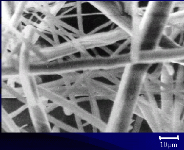
original basalt fibers
|
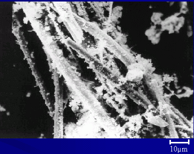
basalt fibers treated with adhesive |
|
|
Morphological analysis of debris
| Original components
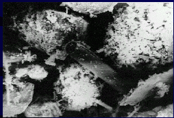
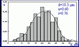 Filler particle distribution by size
| Adhesive wear
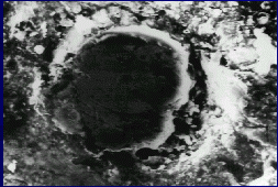
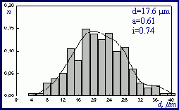 Plasticized material debris distribution by size
| Abrasive wear
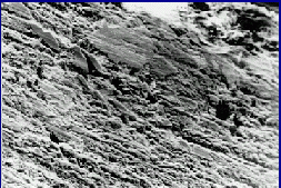
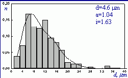 Distribution of debris by size of plasticized material with fillers preliminary treated by adhesives
|
|
|
Porous structure of the frictional material
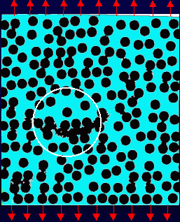 The mainline crack position at uniaxial tension
|
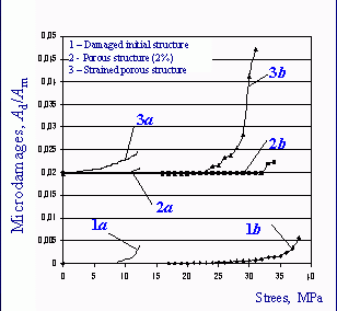 Dependence of damageability on tensile (a) and compressive (b) stresses
|
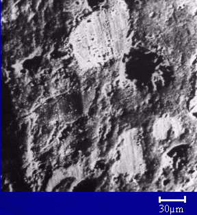 Pores on the friction surface
|
|
|
Nucleation and propagation mechanisms of microcracks in frictional composites
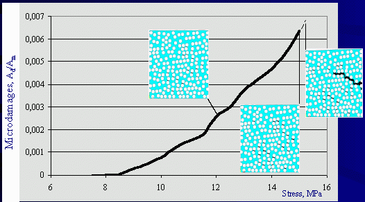 Dependence of microdamageability on loading at uniaxial tension
|
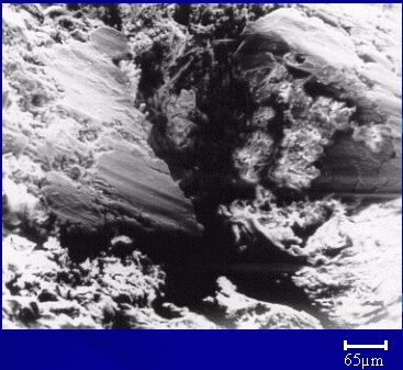 Microcrack on the friction surface
|
|
|
Computing scheme of frictional joints and machine parts by the finite element method
| |
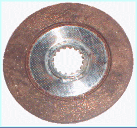 | Creation of virtual model for a real object
|
|
Optimization of design, technology and material: corrective action | |
 |
 |

|
|
Experimental data (bench test and other) |
|
|
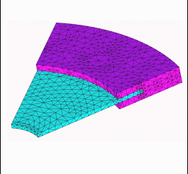 |
Creation of finite-element model
|
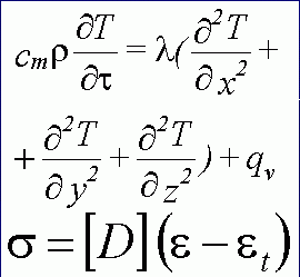 | Solution: computation of temperature, stress and strain
|
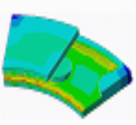 | Analysis of computation results and their comparison with experimental data
|
|
Design optimization of friction metal-polymer ware
|
a b | basic and optimized designs of the metal backing of braking disk
|
c d |
Mises distribution of equivalent stresses over outer contact and inner surface of the friction lining conjugated with the metal backing for the basic and optimized designs | |
|
|
Asbestos-free frictional materials
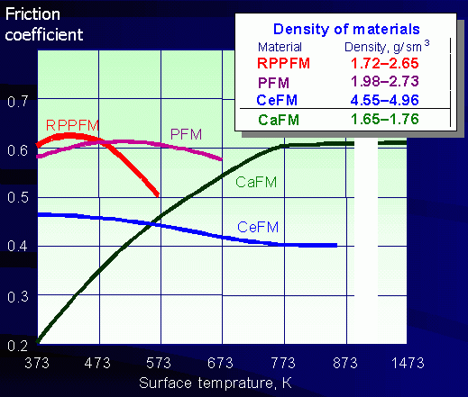 Technical characteristics of frictional materials Technical characteristics of frictional materials
|
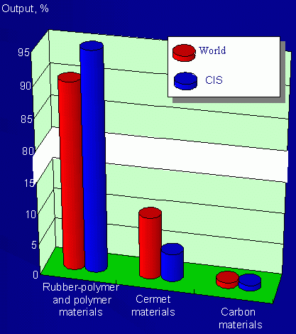 Production structure Production structure
|
|
|
A frictional contact model for a disk brake
 Brake disk Brake disk
|
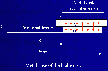
|
Heat models of the frictional contact
|
|
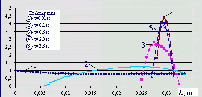
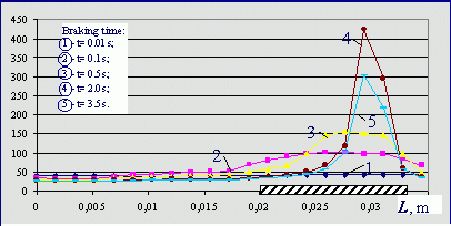
Results of solving the problem of a thermal contact at nonstationary friction and movable contact interface

Braking time t=0.1 s
sz min = -10.8 MPa
sz max = 8.8 MPa
|
 p,
p,
MPa
Distribution of contact pressures across the frictional lining width at different braking time
|

Braking time t=0.5 s
sz min = -14.2 MPa
sz max = 32.2 MPa
 Braking time t=2.0 s
sz min = -33.8 MPa
sz max = 16.9 MPa
|
 T, °C
T, °C
Temperature distribution across the frictional lining width at different braking time
 Braking time t=tB=3.5 s
sz min = -19.7 MPa
sz max = 6.9 MPa
| | |
|
|
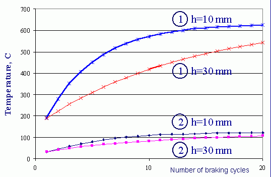
Temperature dependence on the frictional lining surface upon number of brakings
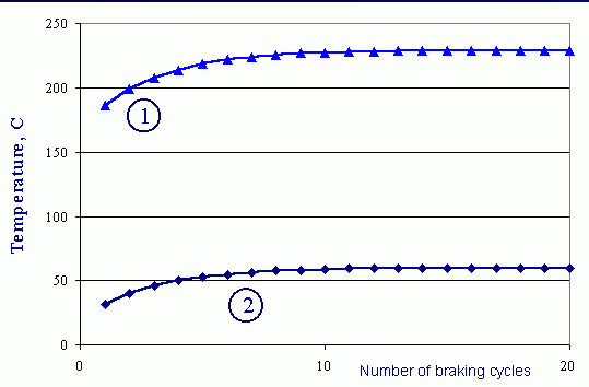
heat model 1
Cyclogram of disk brake loading
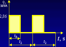 |
braking time tB = 3,5 s
cooling time of rubbing surface t2-tB
a single cycle duration t2= 270 s
|
|
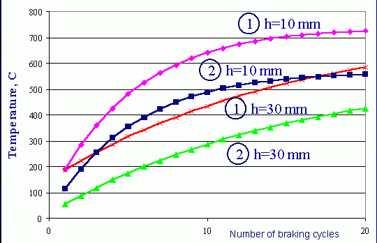
heat model 2
1 - at the end of each braking cycle
2 - at the beginning of each following braking cycle
h - counterbody thickness
|
|
|
Temperature dependence on the counterbofy surface upon number of brakings
heat model 1
Cyclogram of disk brake loading
 |
braking time tB = 3,5 s
cooling time of rubbing surface t2-tB
a single cycle duration t2= 270 s
|
|
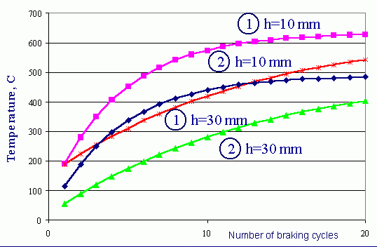
heat model 2
1 - at the end of each braking cycle
2 - at the beginning of each following braking cycle
h - counterbody thickness
|
|
|
Temperature distribution across friction pair thickness
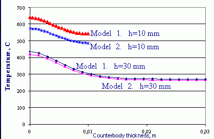
in metal counterbody
Cyclogram of disk brake loading
 |
braking time tB = 3,5 s
cooling time of rubbing surface t2-tB
a single cycle duration t2= 270 s
|
|
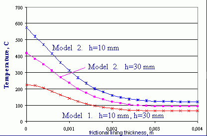
number of braking cycles - 10
h - counterbody thickness
|
|
|
A set of technical facilities for technological diagnostics of frictional materials
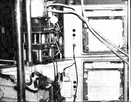
|
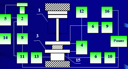
1 – Hydraulic press
2 – pellet mold
3 – plane-parallel plates
4, 5, 15 – displacement and force grauges
|
6, 7, 8 – temperature gauges
9, 10, 11 – control units
12, 13, 14 – recording instruments |
|
|
|
Determined technological parameters of frictional materials
 r – material density
P – minimal pressing pressure
|
1.70 - 2.25 (g/cm3)
36.2 - 99.3 (MPa)
 a – thermal diffusivity
|
0.156 - 0.208 (mm2/s)
 tT – time of viscoplastic flow
µ – viscosity factor
t0 – yield stress
t0 – curing time
|
63 - 140 (s)
42-198 (MPa)
0.20 - 2.16 (MPa)
102 - 285 (s) under pressing temperature Qp=428 °K
 C – cross-linking degree
U – activation energy
|
0.85 - 0.90 (rel. un.)
6.83 - 29.40 (kJ/mol)
 Ks – lateral pressure ratio
f – external friction coefficient
|
0.18 - 0.44 (rel. un.)
0.17 - 0.72 (rel. un.) under pressing pressure 56 MPa
 W – moisture and volatile products content isolating during pressing
|
0.2 - 7.0 (wt. %)
| | | | | |
|
|
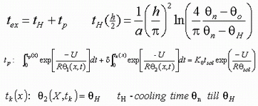
Computation of pressing parameters of frictional parts
Weight mass
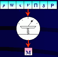
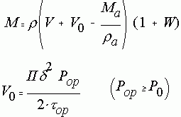
V0 – volume of fin
|
Pressing force
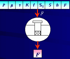

Pop, top, fp – upper limits of 95-% confidence interval
|
Time of exposure under pressure
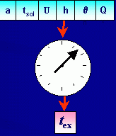
|
|
|
Applied aspects of the development
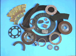
Developed materials
|
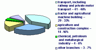
Anticipated pattern of consumption of frictional materials in 2003-2005
|
Technical characteristics
|
Parameter |
Brake materials (dry friction) |
Brake materials (in oils) |
Clutch lining materials|
Density 103 kg/m3 |
2.00-2.46 |
1.86-2.13 |
1.86-2.09
Friction coefficient (P = 1 MPa, V = 2 m/s)
- dry friction
- friction in oil |
0.41-0.62
- |
-0.11-0.15 |
0.58-0.66
-|
Wear rate, Ih 10 -8 |
3.1-5.0 |
0.01 mm in 10 h |
0.68-3.74|
Durable thermal stability, °K, above |
643 |
503 |
623|
Hardness, HB, 10/250/30 |
17.6-46.3 |
7.0-19.6 |
19.1-26.7 | | | | | | |
|
Conclusions
- The cause of wear at outer friction in highly filled frictional materials containing structural plasticizers of non-elastomeric type is largely attributed to formation of weak boundary layers. This occurs as a result of adsorption of the liquid phase of the plasticizer on fiber and dispersed filler surfaces, which proves the adhesive mechanism of wearing of such systems.
- Treatment of mineral fibers as constituents of the fibrous component of frictional materials with active towards matrix polymers adhesives makes it possible to improve wear resistance, stiffness and thermal strength of the composites.
- Heat models of the frictional contact have been proposed to take into account redistribution of heat flows in the rubbing bodies during their interactions. As a result of intensive heat liberation at multiple braking in conditions of dry friction the actual contact area of the frictional contact has been found to diminish from 30% down to the initial contour one. This is considered to be the reason of strong inhomogeneity of temperature fields, essential rise of surface temperatures and thermal stresses in the rubbing bodies.
- Physical principles of conformity of processing characteristics of the polymer frictional materials to preset quality indices of final products have been formulated. Optimization of processing regimes with allowance for inhomogeneity of asbestos-free frictional materials is shown to ameliorate stability of friction parameters and reduce macroinhomogeneity of physico-mechanical properties of frictional parts.
|
|
|

